Automatic Labeling
The automatic labeling feature generates labels for specified objects in the drawing views of the active document.
-
Beam profile labels
-
Equipment labels – Includes the "Name of object" (nam) and "Equipment Position Id" (.n5) attributes, and the positions of structural components.
-
Instrument labels – Includes the "Instrument Position Id" (ipo) attribute.
-
Isometric labels – For pipes with isometric drawings.
-
Part number labels
-
Pipeline labels – Based on the label defined in the script.
-
Primary support labels – Includes the support position and other data defined in the label.
-
Spool labels
-
Valve labels – Includes the "Valve Position Id" (vpo) attribute.
Additionally, a separate command can generate labels for dimension lines of type Continuous dimension or Basepoint dimension inserted with the Automatic Dimensions tool.
The program strives to arrange the labels neatly within the available empty space. If necessary, you can manually adjust the results.
Performing automatic labeling
You can run automatic labeling for specified drawing views in the active document.
Prerequisites
-
Administrator has defined the required configurations, such as Labeling Styles, Automatic Labeling Settings, Label Definitions, and Annotation Property Defaults.
-
The drawing views to be labeled already contain the required dimension lines and other annotations that may affect the generating and positioning of labels.
Do the following:
-
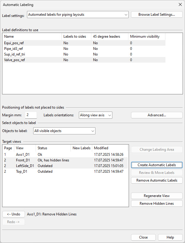
In the document editor, select Home tab > Automatic labeling. The Automatic Labeling dialog opens.
-
Label settings – Use the drop-down menu or click Browse Label Settings to select the Automatic Labeling Settings to use.
-
Label definitions to use – Select the Label Definitions to use for generating labels. Hold down Ctrl or Shift to select multiple items.
-
Positioning of labels not placed to sides – Define how to position labels when the label settings do not require using the sides of the drawing. Experimentation may be necessary to determine what works best for different types of views.
-
Margin mm – Specify how much space to leave around the labels.
-
Labels orientations – Specify how the labels should be oriented: horizontally, vertically, or along the view axis.
-
Advanced – Opens the Advanced Settings dialog for adjusting the parameters of the labeling process.
-
-
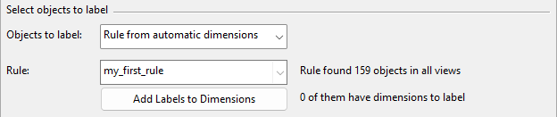
Select objects to label – Specify how the Create Automatic Labels command determines which objects to label. An object to be labeled must be visible in the target view, located within the labeling area, and matched by a label definition included in the labeling operation.
-
Objects to label – Select the required method:
-
All visible objects – Select this option to label all visible objects.
-
Objects in BOM group – Select this option to label the objects assigned to the BOM group of the document.
-
Click Modify Set to choose the objects.
-
Click Browse Set to show the objects in a separate view.
-
-
Define set – Select this option to label a user-defined set of objects.
-
Click Define Set to choose the objects.
-
Click Browse Set to show the objects in a separate view.
-
-
Rule from automatic dimensions – Select this option and then a dimensioning rule from the Rule list to label the objects that match the rule.
Additionally, you can click Add Labels to Dimensions to immediately add labels next to the dimensions created using Automatic Dimensions, regardless of the labeling area limits and the label definition's positioning settings. This command places labels in the views specified by the dimensioning rule, whereas the Create Automatic Labels function uses the target view selections below.
-
-
-
Target views – This pane lists the drawing views assigned to pages in the active document and their current automatic labeling status.
 Show/hide details
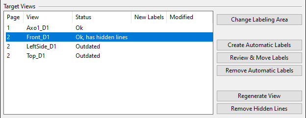
The columns of the pane:
-
Page shows the page number of the view.
-
View shows the name of the view.
-
Status shows the labeling status of the view.
Show/hide details
-
"Ok" – The view is up-to-date in regard to the 3D model and there are no hidden line. You can create automatic labels for the view.
-
"Ok, has hidden lines" – The view is up-to-date in regard to the 3D model, but the view displays hidden lines. Remove the hidden lines before creating automatic labels.
-
"Outdated" – The view is not up-to-date in regard to the 3D model. Regenerate the view and remove hidden lines before creating automatic labels.
-
-
New Labels shows the number of labels that were added to the view in the most recent run.
-
Modified shows the time when automatic labeling was last performed for the view.
Selecting one or several views from the list enables the relevant commands on the right.
-
Change Labeling Area – The objects to be labeled must be inside the labeling area. Using this command, you can adjust the labeling area of the selected view by picking the start point and end point of the rectangular area, or restore its default width and height by selecting Use default extents from the context menu.
-
Create Automatic Labels – Select this command to run the automatic labeling process for the selected views.
Before the labeling starts, the following might happen:
-
If any of the selected views have hidden lines, or the views are outdated, or there are other issues that could affect the results, you are prompted to select how to proceed.
-
If annotation property defaults have not been selected for this drawing, you are prompted to select the settings to use.
-
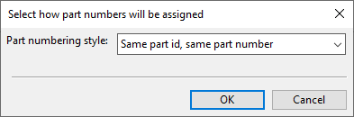
If the label definition creates part number labels, you are prompted to select how the numbers should be assigned.
Show/hide details
-
Do not assign new part numbers
-
Each part has its own part number
-
Same part id, same part number (default)
-
Same geometric shape, same part number
-
While the labeling process runs, you can stop it anytime. Stopping the process before it completes prompts you to choose whether to keep the already inserted labels.
-
-
Review & Move Labels – Select this command to reposition labels by clicking a label and then clicking again to accept its new position.
-
Remove Automatic Labels – Select this command to remove automatically inserted labels from the selected views, including those inserted with Add Labels to Dimensions.
-
Regenerate View – Select this command to regenerate the selected views to match the current 3D model. For more information on this, see Regenerate.
-
Remove Hidden Lines – Select this command to remove hidden lines from the selected, regenerated views. For more information on this, see Remove Hidden Lines.
-
-
You can use the Undo and Redo buttons to undo or redo your actions. For example, if you remove the inserted labels, you can restore them with Undo, instead of having to run the placement process again.
-
Click Close.
Advanced Settings
In the Advanced Settings dialog of automatic labeling, you can define the following settings.
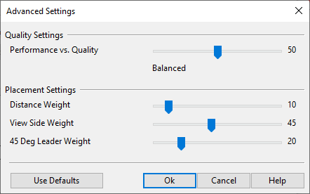
Quality Settings
-
Performance vs. Quality – Adjusts the balance between performance and quality.
-
Drag the slider to the left for faster results.
-
Drag the slider to the right for improved label positioning quality.
-
Placement Settings
-
Distance Weight – Controls the distance between the label and the target object.
-
Drag the slider to the left to position labels farther away from the target objects.
-
Drag the slider to the right to position labels closer to the target objects.
-